

|
|
TI Automotive and Industrial mmWave Radar products are highly-integrated 77GHz CMOS millimeter wave devices.The devices integrate all of the RF and Analog functionality, including VCO, PLL, PA, LNA, Mixer and ADC for multiple TX/RX channels into a single chip.
TI mmWave radar devices include a mmwave front end or BIST (Built-in Self-Test) processor, which is responsible to configure the RF/Analog and digital front-end in real-time, as well as to periodically schedule calibration and functional safety monitoring.This enables the mmwave front-end(BIST processor) to be self-contained and capable of adapting itself to handle temperature and ageing effects, and to enable significant ease-of-use from an external host perspective.
TI mmwave front end is a closed subsystem whose internal blocks are configurable using messages coming over mailbox.
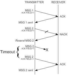
TI mmWaveLink provides APIs generates these message and sends it to mmwave front end over mailbox. It also includes acknowledement and CRC for each message to provide a reliable communication
TI mmWaveLink Framework:
Is integrated into mmWave SDK and can run on R4F or DSP and communicates with mmwave front end over Mailbox interface
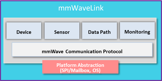
To make it simple, TI's mmWaveLink framework capabilities are divided into modules.
These capabilities include device control, RF/Analog configuration, ADC configuration, Data path(LVDS/CSI2) cofiguration, FMCW chirp configuration and more.
Listed below are the various modules in the mmWaveLink framework:
 Initialization, such as: mmwave device power On/Off, Firmware Patch download
 Cascade device configuration such as Add/Connect multiple mmWave devices
Sensor - The RF/Sensor Configuration module controls the different HW blocks inside mmWave Front end.
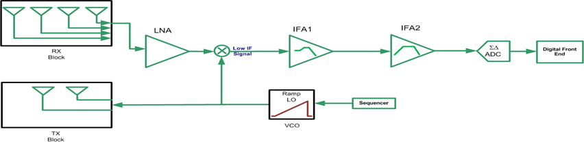
mmWave Front End has below key blocks
The configuration APIs can further be categorized as.
Data Path - The Data path Configuration module controls the high speed interface in mmWave device.
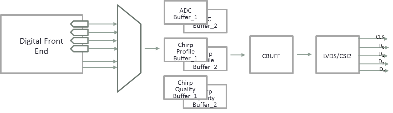
The configuration APIs include.
Monitoring - The Monitoring/Calibration module configures the calibration and functional safety monitoring in mmWave device
TI mmWave Front end includes built-in processor that is programmed by TI to handle RF calibrations and functional safety monitoring. The RF calibrations ensure that the performance of the device is maintained across temperature and process corners
If Command can not be processed immediately, ACK response is sent immediately (If requested). "Asynchronous Event" is sent upon completion of the command execution.
The porting of the mmWaveLink driver to any new platform is based on few simple steps. This guide takes you through this process step by step. Please follow the instructions carefully to avoid any problems during this process and to enable efficient and proper work with the device. Please notice that all modifications and porting adjustments of the driver should be made in the application only and driver should not be modified. Changes in the application file will ensure smoothly transaction to new versions of the driver at the future!
The mmWaveLink framework is ported to different platforms using mmWaveLink client callbacks. These callbacks are grouped as different structures such as OS callbacks, Communication Interface callbacks and others. Application needs to define these callbacks and initialize the mmWaveLink framework with the structure.
Refer to rlClientCbs_t for more details
The mmWaveLink device support several standard communication protocol among SPI and MailBox Depending on device variant, one need to choose the communication channel. For e.g xWR1443/xWR1642/xWR1843 requires Mailbox interface and AWR1243 supports SPI interface. The interface for this communication channel should include 4 simple access functions:
Refer to rlComIfCbs_t for interface details
The mmWaveLink driver internally powers on/off the mmWave radar device. The exact implementation of these interface is platform dependent, hence you need to implement below functions:
Refer to rlDeviceCtrlCbs_t for interface details
The mmWaveLink driver reports asynchronous event indicating mmwave radar device status, exceptions etc. Application can register this callback to receive these notification and take appropriate actions
Refer to rlEventCbs_t for interface details
The mmWaveLink driver can work in both OS and NonOS environment. If Application prefers to use operating system, it needs to implement basic OS routines such as tasks, mutex and Semaphore
Refer to rlOsiCbs_t for interface details
The mmWaveLink driver uses CRC for message integrity. If Application prefers to use CRC, it needs to implement CRC routine.
Refer to rlCrcCbs_t for interface details
The mmWaveLink driver can print the debug message. If Application prefers to enable debug messages, it needs to implement debug callback.
Refer to rlDbgCb_t for interface details
Once all the above Interfaces are implemented, Application need to fill these callbacks in rlClientCbs_t and Initialize mmWaveLink by passing the client callbacks. Application also need to define where the mmWaveLink driver is running, for e.g, External Host in case of AWR1243 or MSS/DSS in case of xWR1642/xWR1843.
The mmWaveLink driver by default is enabled for Little Endian host. Support for Big Endian is provided as compile time option using a Pre-processor Macro MMWL_BIG_ENDIAN.
For memory optimizations, mmWaveLink doesn't swap the data elements in structure buffer. It is the responsibility of the application to swap multi byte data elements before passing the structure buffer to mmWaveLink API. Since SPI word-size is 16bit, Swap of 32 bit fields such as integer needs to be done at 16bit boundary.