

|
|
mmwave radar RF/Sensor Configuration Module More...
Functions | |
| MMWL_EXPORT rlReturnVal_t | rlSetChannelConfig (rlUInt8_t deviceMap, rlChanCfg_t *data) |
| Sets the Rx and Tx Channel Configuration. More... | |
| MMWL_EXPORT rlReturnVal_t | rlSetAdcOutConfig (rlUInt8_t deviceMap, rlAdcOutCfg_t *data) |
| Sets ADC Output Configuration. More... | |
| MMWL_EXPORT rlReturnVal_t | rlSetLowPowerModeConfig (rlUInt8_t deviceMap, rlLowPowerModeCfg_t *data) |
| Sets Low Power Mode Configuration. More... | |
| MMWL_EXPORT rlReturnVal_t | rlRfInit (rlUInt8_t deviceMap) |
| Initializes the RF/Analog Subsystem. More... | |
| MMWL_EXPORT rlReturnVal_t | rlGetProfileConfig (rlUInt8_t deviceMap, rlUInt16_t profileId, rlProfileCfg_t *data) |
| Gets Chirp profile Configuration. More... | |
| MMWL_EXPORT rlReturnVal_t | rlSetProfileConfig (rlUInt8_t deviceMap, rlUInt16_t cnt, rlProfileCfg_t *data) |
| Sets Chirp profile Configuration. More... | |
| MMWL_EXPORT rlReturnVal_t | rlGetChirpConfig (rlUInt8_t deviceMap, rlUInt16_t chirpStartIdx, rlUInt16_t chirpEndIdx, rlChirpCfg_t *data) |
| Gets Chirp Configuration. More... | |
| MMWL_EXPORT rlReturnVal_t | rlSetChirpConfig (rlUInt8_t deviceMap, rlUInt16_t cnt, rlChirpCfg_t *data) |
| Sets Chirp Configuration. More... | |
| MMWL_EXPORT rlReturnVal_t | rlSetMultiChirpCfg (rlUInt8_t deviceMap, rlUInt16_t cnt, rlChirpCfg_t **data) |
| Injects chirp configuration to be programmed dynamically. More... | |
| MMWL_EXPORT rlReturnVal_t | rlGetFrameConfig (rlUInt8_t deviceMap, rlFrameCfg_t *data) |
| Gets Frame Configuration. More... | |
| MMWL_EXPORT rlReturnVal_t | rlSetFrameConfig (rlUInt8_t deviceMap, rlFrameCfg_t *data) |
| Sets Frame Configuration. More... | |
| MMWL_EXPORT rlReturnVal_t | rlSensorStart (rlUInt8_t deviceMap) |
| Triggers Transmission of Frames. More... | |
| MMWL_EXPORT rlReturnVal_t | rlSensorStop (rlUInt8_t deviceMap) |
| Stops Transmission of Frames. More... | |
| MMWL_EXPORT rlReturnVal_t | rlGetAdvFrameConfig (rlUInt8_t deviceMap, rlAdvFrameCfg_t *data) |
| Gets Advance Frame Configuration. More... | |
| MMWL_EXPORT rlReturnVal_t | rlSetAdvFrameConfig (rlUInt8_t deviceMap, rlAdvFrameCfg_t *data) |
| Sets Advance Frame Configuration. More... | |
| MMWL_EXPORT rlReturnVal_t | rlSetContModeConfig (rlUInt8_t deviceMap, rlContModeCfg_t *data) |
| Sets Continous mode Configuration. More... | |
| MMWL_EXPORT rlReturnVal_t | rlEnableContMode (rlUInt8_t deviceMap, rlContModeEn_t *data) |
| Enable/Disable Continous mode. More... | |
| MMWL_EXPORT rlReturnVal_t | rlSetBpmCommonConfig (rlUInt8_t deviceMap, rlBpmCommonCfg_t *data) |
| Sets Binary Phase Modulation Common Configuration. More... | |
| MMWL_EXPORT rlReturnVal_t | rlSetBpmChirpConfig (rlUInt8_t deviceMap, rlBpmChirpCfg_t *data) |
| Sets Binary Phase Modulation Chirp Configuration. More... | |
| MMWL_EXPORT rlReturnVal_t | rlSetMultiBpmChirpConfig (rlUInt8_t deviceMap, rlUInt16_t cnt, rlBpmChirpCfg_t **data) |
| Sets Binary Phase Modulation configuration for multiple Chirp. More... | |
| MMWL_EXPORT rlReturnVal_t | rlSetTestSourceConfig (rlUInt8_t deviceMap, rlTestSource_t *data) |
| Configures the Test Source. More... | |
| MMWL_EXPORT rlReturnVal_t | rlTestSourceEnable (rlUInt8_t deviceMap, rlTestSourceEnable_t *data) |
| Enables the Test Source. More... | |
| MMWL_EXPORT rlReturnVal_t | rlRfGetTemperatureReport (rlUInt8_t deviceMap, rlRfTempData_t *data) |
| Gets Time and Temperature information report. More... | |
| MMWL_EXPORT rlReturnVal_t | rlRfDfeRxStatisticsReport (rlUInt8_t deviceMap, rlDfeStatReport_t *data) |
| Gets Digital Front end statistics such as Residual DC, RMS power in I and Q chains for different Receive channels for different selected profiles. It also includes Cross correlation between I and Q chains. More... | |
| MMWL_EXPORT rlReturnVal_t | rlRfDynamicPowerSave (rlUInt8_t deviceMap, rlDynPwrSave_t *data) |
| : Configure dynamic power saving feature. More... | |
| MMWL_EXPORT rlReturnVal_t | rlRfSetDeviceCfg (rlUInt8_t deviceMap, rlRfDevCfg_t *data) |
| : Set different RadarSS device configurations More... | |
| MMWL_EXPORT rlReturnVal_t | rlSetGpAdcConfig (rlUInt8_t deviceMap, rlGpAdcCfg_t *data) |
| : Configure GP ADC data parameters More... | |
| MMWL_EXPORT rlReturnVal_t | rlRfSetPhaseShiftConfig (rlUInt8_t deviceMap, rlUInt16_t cnt, rlRfPhaseShiftCfg_t *data) |
| Enable/Disable phase shift configurations per chirp in each of the TXs. More... | |
| MMWL_EXPORT rlReturnVal_t | rlRfSetPALoopbackConfig (rlUInt8_t deviceMap, rlRfPALoopbackCfg_t *data) |
| Enable/Disable PA loopback for all enabled profiles. More... | |
| MMWL_EXPORT rlReturnVal_t | rlRfSetPSLoopbackConfig (rlUInt8_t deviceMap, rlRfPSLoopbackCfg_t *data) |
| Enable/Disable Phase shift loopback for all enabled profiles. More... | |
| MMWL_EXPORT rlReturnVal_t | rlRfSetIFLoopbackConfig (rlUInt8_t deviceMap, rlRfIFLoopbackCfg_t *data) |
| Enable/Disable RF IF loopback for all enabled profiles. This is used for debug to check if both TX and RX chains are working correctly. More... | |
| MMWL_EXPORT rlReturnVal_t | rlRfSetProgFiltCoeffRam (rlUInt8_t deviceMap, rlRfProgFiltCoeff_t *data) |
| Set Programmable Filter coefficient RAM. More... | |
| MMWL_EXPORT rlReturnVal_t | rlRfSetProgFiltConfig (rlUInt8_t deviceMap, rlRfProgFiltConf_t *data) |
| Set Programmable Filter configuration. More... | |
| MMWL_EXPORT rlReturnVal_t | rlRfSetMiscConfig (rlUInt8_t deviceMap, rlRfMiscConf_t *data) |
| Sets misc feature such as per chirp phase shifter. More... | |
| MMWL_EXPORT rlReturnVal_t | rlRfSetCalMonTimeUnitConfig (rlUInt8_t deviceMap, rlRfCalMonTimeUntConf_t *data) |
| Set Calibration monitoring time unit. More... | |
| MMWL_EXPORT rlReturnVal_t | rlRfSetCalMonFreqLimitConfig (rlUInt8_t deviceMap, rlRfCalMonFreqLimitConf_t *data) |
| Set Calibration monitoring Frequency Limit. More... | |
| MMWL_EXPORT rlReturnVal_t | rlRfInitCalibConfig (rlUInt8_t deviceMap, rlRfInitCalConf_t *data) |
| Set RF Init Calibration Mask bits and report type. More... | |
| MMWL_EXPORT rlReturnVal_t | rlRfRunTimeCalibConfig (rlUInt8_t deviceMap, rlRunTimeCalibConf_t *data) |
| Set RF one time & periodic calibration of various RF/analog aspects and trigger. More... | |
| MMWL_EXPORT rlReturnVal_t | rlRxGainTempLutSet (rlUInt8_t deviceMap, rlRxGainTempLutData_t *data) |
| Overwrite RX gain temperature Lookup Table(LUT) in Radar SS. More... | |
| MMWL_EXPORT rlReturnVal_t | rlTxGainTempLutSet (rlUInt8_t deviceMap, rlTxGainTempLutData_t *data) |
| Overwrites TX gain temperature based Lookup table (LUT) More... | |
| MMWL_EXPORT rlReturnVal_t | rlRfTxFreqPwrLimitConfig (rlUInt8_t deviceMap, rlRfTxFreqPwrLimitMonConf_t *data) |
| Sets the limits for RF frequency transmission for each TX and also TX power limits. More... | |
| MMWL_EXPORT rlReturnVal_t | rlSetLoopBckBurstCfg (rlUInt8_t deviceMap, rlLoopbackBurst_t *data) |
| This API is used to introduce loopback chirps within the functional frames. More... | |
| MMWL_EXPORT rlReturnVal_t | rlSetDynChirpCfg (rlUInt8_t deviceMap, rlUInt16_t segCnt, rlDynChirpCfg_t **data) |
| Injects chirp configuration to be programmed dynamically. More... | |
| MMWL_EXPORT rlReturnVal_t | rlSetDynChirpEn (rlUInt8_t deviceMap, rlDynChirpEnCfg_t *data) |
| Triggers copy of chirp config from SW to HW RAM. More... | |
| MMWL_EXPORT rlReturnVal_t | rlRfCalibDataStore (rlUInt8_t deviceMap, rlCalibrationData_t *data) |
| Read calibration data from the device. More... | |
| MMWL_EXPORT rlReturnVal_t | rlRfCalibDataRestore (rlUInt8_t deviceMap, rlCalibrationData_t *data) |
| Injects calibration data to the device. More... | |
| MMWL_EXPORT rlReturnVal_t | rlRfInterRxGainPhaseConfig (rlUInt8_t deviceMap, rlInterRxGainPhConf_t *data) |
| Sets different Rx gain/phase offset. More... | |
| MMWL_EXPORT rlReturnVal_t | rlGetRfBootupStatus (rlUInt8_t deviceMap, rlRfBootStatusCfg_t *data) |
| Get radarSS bootup status. More... | |
| MMWL_EXPORT rlReturnVal_t | rlSetInterChirpBlkCtrl (rlUInt8_t deviceMap, rlInterChirpBlkCtrlCfg_t *data) |
| Sets Inter-chip turn on and turn off times or various RF blocks. More... | |
| MMWL_EXPORT rlReturnVal_t | rlSetSubFrameStart (rlUInt8_t deviceMap, rlSubFrameStartCfg_t *data) |
| Triggers the next sub-frame in software triggered sub-frame mode. More... | |
| MMWL_EXPORT rlReturnVal_t | rlRfPhShiftCalibDataStore (rlUInt8_t deviceMap, rlPhShiftCalibrationData_t *data) |
| Read calibration data from the device. More... | |
| MMWL_EXPORT rlReturnVal_t | rlRfPhShiftCalibDataRestore (rlUInt8_t deviceMap, rlPhShiftCalibrationData_t *data) |
| Injects phase shifter calibration data to the device. More... | |
| MMWL_EXPORT rlReturnVal_t | rlGetRfDieId (rlUInt8_t deviceMap, rlRfDieIdCfg_t *data) |
| Get device die ID status. More... | |
mmwave radar RF/Sensor Configuration Module
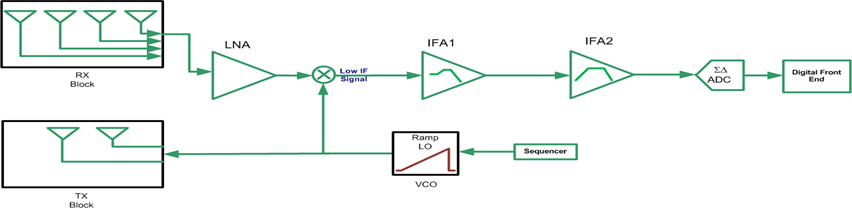
The RF/Sensor Configuration module controls the different HW blocks inside mmWave Front end. mmWave Front End has below key blocks
The Sensor Control APIs needs to be called by application in below sequence
Application should first configure the mmWave Front end or Radar SS with below Static configurations
After initial static configurations, application should initialize RF and shall wait for calibration complete Asynchornous event RL_RF_AE_INITCALIBSTATUS_SB
After RF initilization, Application can configure chirps and frame using below APIs
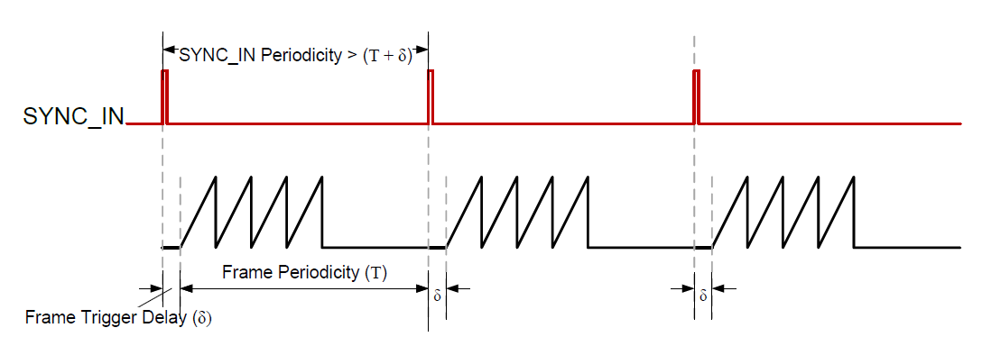
Frame Configuration - rlSetFrameConfig or rlSetAdvFrameConfig Note about HW SYNC_IN pulse in hardware triggered mode
a. The SYNC_IN pulse must not arrive before the frame end boundary b. If frame trigger delay is used with hardware triggered mode, then external SYNC_IN pulse periodicity should take care of the configured frame trigger delay and frame periodicity. The external pulse should be issued only after the sum total of frame trigger delay and frame periodicity. See figure below
c. The inter frame blank time should be at least 250 uS(100 uS for frame preparation and 150 uS for any calibration updates to hardware). Add 150 uS to inter-frame blank time for test source configuration if test source is enabled.
After All the configuration, Application can use Sensor Start API to start Frame and shall wait for Frame Ready Asynchronous event RL_RF_AE_FRAME_TRIGGER_RDY_SB
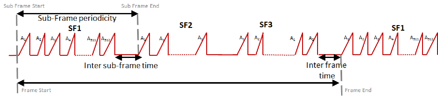
Legacy frame config API rlSetFrameConfig supports looping of the same FMCW frame. In order to configure multiple FMCW frames with different chirp profiles, user needs to use rlSetAdvFrameConfig API. Advance Frame consists of one or upto 4 Sub-Frames Each Sub-Frame consists of multiple bursts. Each burst consists of multiple chirps as shown in diagram below.
To enable Advance Frame, Application needs to follow below sequence
Using Legacy chirp configuration API rlSetChirpConfig, chirps can't be re-configure without stopping the ongoing FMCW frame using rlSensorStop API.
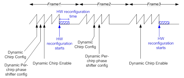
If user needs to re-configure chirp during the frame, it needs to use Dynamic chirp config APIs. Once the API is received by mmWave Front end, it would re-configure the chirps for next FMCW frame. Dynamic Chirps can be defined using below APIs
Diagram below shows the Dynamic Chirp behaviour. Note that since dynamic chirps are configured at run time, there is not error checks done on the input data. If input data is out of range or invalid, device might misbehave.
TI mmWave Front end includes built-in processor that is programmed by TI to handle RF calibrations and functional safety monitoring. The RF calibrations ensure that the performance of the device is maintained across temperature and process corners
Below is the list of calibrations and corresponding duration in microseconds
Boot Time Calibration
| Calibration | Duration(us) |
|---|---|
| APLL | 330 |
| Synth VCO | 1300 |
| LO DIST | 12 |
| ADC DC | 600 |
| HPF cutoff | 3500 |
| LPF cut off | 3200 |
| Peak detector | 4200 |
| TX power (assumes 2 TX use-case) | 6000 |
| RX gain | 2300 |
| TX phase (not enabled in firmware) | 150 |
| RX IQMM (Not applcicable for Real ADC mode) | 32000 |
Run Time Calibration
| Calibration | Duration(us) |
|---|---|
| APLL | 150 |
| Synth VCO | 300 |
| LO DIST | 30 |
| Peak detector | 500 |
| TX power (assumes 2 TX use-case) | 800 |
| RX gain | 30 |
| Application of calibration to hardware (This needs to be included always) | 150 |
 Related Files
- rl_sensor.c
| rlReturnVal_t rlEnableContMode | ( | rlUInt8_t | deviceMap, |
| rlContModeEn_t * | data | ||
| ) |
Enable/Disable Continous mode.
| [in] | deviceMap | - Bitmap of devices to send the message |
| [in] | data | - Continous Mode enable/disable |
This function enables/disables the FMCW radar continous mode
Definition at line 1291 of file rl_sensor.c.
| rlReturnVal_t rlGetAdvFrameConfig | ( | rlUInt8_t | deviceMap, |
| rlAdvFrameCfg_t * | data | ||
| ) |
Gets Advance Frame Configuration.
| [in] | deviceMap | - Bitmap of devices to send the message |
| [out] | data | - Container for Advance Frame Configuration data |
This function reads the advance frame properties of the device.
Definition at line 1183 of file rl_sensor.c.
| rlReturnVal_t rlGetChirpConfig | ( | rlUInt8_t | deviceMap, |
| rlUInt16_t | chirpStartIdx, | ||
| rlUInt16_t | chirpEndIdx, | ||
| rlChirpCfg_t * | data | ||
| ) |
Gets Chirp Configuration.
| [in] | deviceMap | - Bitmap of devices to send the message |
| [in] | chirpStartIdx | - Chirp Start Index |
| [in] | chirpEndIdx | - Chirp End Index |
| [out] | data | - Container for Chirp Configuration data |
This function gets the chirp configuration from the device.
Definition at line 711 of file rl_sensor.c.
| rlReturnVal_t rlGetFrameConfig | ( | rlUInt8_t | deviceMap, |
| rlFrameCfg_t * | data | ||
| ) |
Gets Frame Configuration.
| [in] | deviceMap | - Bitmap of devices to send the message |
| [out] | data | - Container for Frame Configuration data |
This function reads the frame properties of the device.
Definition at line 1045 of file rl_sensor.c.
| rlReturnVal_t rlGetProfileConfig | ( | rlUInt8_t | deviceMap, |
| rlUInt16_t | profileId, | ||
| rlProfileCfg_t * | data | ||
| ) |
Gets Chirp profile Configuration.
| [in] | deviceMap | - Bitmap of devices to send the message |
| [in] | profileId | - Profile Id |
| [out] | data | - Container for Profile Configuration data |
This function gets the FMCW radar chirp properties like FMCW slope, chirp duration, TX power etc. from the device.
Definition at line 505 of file rl_sensor.c.
| rlReturnVal_t rlGetRfBootupStatus | ( | rlUInt8_t | deviceMap, |
| rlRfBootStatusCfg_t * | data | ||
| ) |
Get radarSS bootup status.
| [in] | deviceMap | - Bitmap of devices to send the message |
| [in] | data | - bootup status configuration |
This API gets the radarSS bootup status
Definition at line 3144 of file rl_sensor.c.
| rlReturnVal_t rlGetRfDieId | ( | rlUInt8_t | deviceMap, |
| rlRfDieIdCfg_t * | data | ||
| ) |
Get device die ID status.
| [in] | deviceMap | - Bitmap of devices to send the message |
| [out] | data | - Die ID status |
This API gets the device Die ID status
Definition at line 3424 of file rl_sensor.c.
| rlReturnVal_t rlRfCalibDataRestore | ( | rlUInt8_t | deviceMap, |
| rlCalibrationData_t * | data | ||
| ) |
Injects calibration data to the device.
| [in] | deviceMap | - Bitmap of devices to send the message |
| [in] | data | - Calibration data of 3 chunks stored at application space |
This API restores the calibration data which was stored previously using the rlCalibDataStore command. Application needs to feed in 3 chunks of calibration data.
Definition at line 2970 of file rl_sensor.c.
| rlReturnVal_t rlRfCalibDataStore | ( | rlUInt8_t | deviceMap, |
| rlCalibrationData_t * | data | ||
| ) |
Read calibration data from the device.
| [in] | deviceMap | - Bitmap of devices to send the message. |
| [in] | data | - Calibration data of 3 chunks which will filled by device. |
This API reads the calibration data from the device which can be injected later using the rlCalibDataRestore command. RadarSS will return 3 chunks of calibration data.
Definition at line 3040 of file rl_sensor.c.
| rlReturnVal_t rlRfDfeRxStatisticsReport | ( | rlUInt8_t | deviceMap, |
| rlDfeStatReport_t * | data | ||
| ) |
Gets Digital Front end statistics such as Residual DC, RMS power in I and Q chains for different Receive channels for different selected profiles. It also includes Cross correlation between I and Q chains.
| [in] | deviceMap | - Bitmap of devices to send the message |
| [in] | data | - Container of dfe receiver status report |
Gets Digital Front end statistics such as Residual DC, RMS power in I and Q chains for different Receive channels for different selected profiles. It also includes Cross correlation between I and Q chains
Definition at line 1637 of file rl_sensor.c.
| rlReturnVal_t rlRfDynamicPowerSave | ( | rlUInt8_t | deviceMap, |
| rlDynPwrSave_t * | data | ||
| ) |
: Configure dynamic power saving feature.
| [in] | deviceMap | - Bitmap of devices to send the message |
| [in] | data | - Container of dynamic power save information |
Configure dynamic power saving feature during Inter chirp Idle time by turning off various circuits such as Transmitter, Receiver and LO distribution blocks
Definition at line 1682 of file rl_sensor.c.
| rlReturnVal_t rlRfGetTemperatureReport | ( | rlUInt8_t | deviceMap, |
| rlRfTempData_t * | data | ||
| ) |
Gets Time and Temperature information report.
| [in] | deviceMap | - Bitmap of devices to send the message |
| [out] | data | - Structure to store temperature report from all the temp sensors |
This function reads Temperature information from all temperature sensors in the device
Definition at line 1595 of file rl_sensor.c.
| rlReturnVal_t rlRfInit | ( | rlUInt8_t | deviceMap | ) |
Initializes the RF/Analog Subsystem.
| [in] | deviceMap | - Bitmap of devices to send the message |
Initializes the RF/Analog Subsystem. This triggers one time calibrations for APLL and synthesizer. Calibration can be enabled/disabled using Calibraton configuration APIs
Definition at line 1470 of file rl_sensor.c.
| rlReturnVal_t rlRfInitCalibConfig | ( | rlUInt8_t | deviceMap, |
| rlRfInitCalConf_t * | data | ||
| ) |
Set RF Init Calibration Mask bits and report type.
| [in] | deviceMap | - Bitmap of devices to send the message |
| [in] | data | - RF Init calib config |
This function configures RF Init calibration mask bits and report type. Normally, upon receiving rlRfInit API, the Radar SS performs all relevant initial calibrations. This step can be disabled by setting the corresponding bit in rlRfInitCalConf_t field to 0x0.If disabled, the host needs to send the calibration data using rlRfCalibDataRestore so that the RadarSS can operate using the injected calibration data
Definition at line 2320 of file rl_sensor.c.
| rlReturnVal_t rlRfInterRxGainPhaseConfig | ( | rlUInt8_t | deviceMap, |
| rlInterRxGainPhConf_t * | data | ||
| ) |
Sets different Rx gain/phase offset.
| [in] | deviceMap | - Bitmap of devices to send the message |
| [in] | data | - Inter RX gain, phase offset config |
This API can be used to induce different gain/phase offsets on the different RXs, for inter-RX mismatch compensation.
Definition at line 3109 of file rl_sensor.c.
| rlReturnVal_t rlRfPhShiftCalibDataRestore | ( | rlUInt8_t | deviceMap, |
| rlPhShiftCalibrationData_t * | data | ||
| ) |
Injects phase shifter calibration data to the device.
| [in] | deviceMap | - Bitmap of devices to send the message |
| [in] | data | - Calibration data of number of TX channels enabled chunks stored at application space |
This API restores the phase shifter calibration data which was stored previously using the rlRfPhShiftCalibDataStore command. Application needs to feed number of TX channels enabled chunks of phase shifter calibration data. This is device specific feature, please refer data sheet.
Definition at line 3273 of file rl_sensor.c.
| rlReturnVal_t rlRfPhShiftCalibDataStore | ( | rlUInt8_t | deviceMap, |
| rlPhShiftCalibrationData_t * | data | ||
| ) |
Read calibration data from the device.
| [in] | deviceMap | - Bitmap of devices to send the message. |
| [in] | data | - Phase shift calibration data of number of TX channels enbled chunks which will filled by device. |
This API reads the phase shifter calibration data from the device which can be injected later using the rlRfPhShifterCalibDataRestore command. RadarSS will return number of TX chunks of phase shifter calibration data.This is device specific feature, please refer data sheet.
Definition at line 3348 of file rl_sensor.c.
| rlReturnVal_t rlRfRunTimeCalibConfig | ( | rlUInt8_t | deviceMap, |
| rlRunTimeCalibConf_t * | data | ||
| ) |
Set RF one time & periodic calibration of various RF/analog aspects and trigger.
| [in] | deviceMap | - Bitmap of devices to send the message |
| [in] | data | - Runtime calibration config |
This function configures RF one time & periodic calibration of various RF/analog aspects and trigger. The response is in the form of an asynchronous event. The calibration would be performed by Radar SS during while framing during any idle time slot of 200uS
Definition at line 2365 of file rl_sensor.c.
| rlReturnVal_t rlRfSetCalMonFreqLimitConfig | ( | rlUInt8_t | deviceMap, |
| rlRfCalMonFreqLimitConf_t * | data | ||
| ) |
Set Calibration monitoring Frequency Limit.
| [in] | deviceMap | - Bitmap of devices to send the message |
| [in] | data | - RF Calib Frequency Limit config |
This function configures limits on RF frequency transmission during calibration and monitoring
Definition at line 2272 of file rl_sensor.c.
| rlReturnVal_t rlRfSetCalMonTimeUnitConfig | ( | rlUInt8_t | deviceMap, |
| rlRfCalMonTimeUntConf_t * | data | ||
| ) |
Set Calibration monitoring time unit.
| [in] | deviceMap | - Bitmap of devices to send the message |
| [in] | data | - RF Calib Monitoring Time unit config |
This function configures calibration monitoring time unit
Definition at line 2229 of file rl_sensor.c.
| rlReturnVal_t rlRfSetDeviceCfg | ( | rlUInt8_t | deviceMap, |
| rlRfDevCfg_t * | data | ||
| ) |
: Set different RadarSS device configurations
| [in] | deviceMap | - Bitmap of devices to send the message |
| [in] | data | - Configuration parameter for AE. |
Set different RadarSS device configurations. Enable and Configure asynchronous event direction for device. By default all asynchronous event are enabled and sent to the platform which issued the API. Below events can be configured to be received on different platform by using this API:
[1.] CPU_FAULT [2.] ESM_FAULT [3.] ANALOG_FAULT Similarly all monitoring events can be configured to be received on specific platform using this API Below events can be disabled using this API:
[1.] FRAME_START_ASYNC_EVENT [2.] FRAME_STOP_ASYNC_EVENT
Enable[1]/Disable[0] RadarSS Watchdog, where by default it is disable. Configure CRC type for asynchronous event from RadarSS [0] 16Bit, [1] 32Bit, [2] 64Bit.
Definition at line 1731 of file rl_sensor.c.
| rlReturnVal_t rlRfSetIFLoopbackConfig | ( | rlUInt8_t | deviceMap, |
| rlRfIFLoopbackCfg_t * | data | ||
| ) |
Enable/Disable RF IF loopback for all enabled profiles. This is used for debug to check if both TX and RX chains are working correctly.
| [in] | deviceMap | - Bitmap of devices to send the message |
| [in] | data | - IF loopback configuration |
This function Enables/Disables RF IF loopback for all enabled profiles. This is used to debug the RX IF chain.
Definition at line 2063 of file rl_sensor.c.
| rlReturnVal_t rlRfSetMiscConfig | ( | rlUInt8_t | deviceMap, |
| rlRfMiscConf_t * | data | ||
| ) |
Sets misc feature such as per chirp phase shifter.
| [in] | deviceMap | - Bitmap of devices to send the message |
| [in] | data | - Misc configuration such as per chirp phase shifter |
This function enables misc feature such as per chirp phase shifter.This API is valid for devices for which phase shifter is enabled(AWR1243P, AWR1843).
Definition at line 2191 of file rl_sensor.c.
| rlReturnVal_t rlRfSetPALoopbackConfig | ( | rlUInt8_t | deviceMap, |
| rlRfPALoopbackCfg_t * | data | ||
| ) |
Enable/Disable PA loopback for all enabled profiles.
| [in] | deviceMap | - Bitmap of devices to send the message |
| [in] | data | - PA loopback configuration |
This function Enables/Disables PA loopback for all enabled profiles. This is used for debug purpose that both the TX and RX paths are working properly
Definition at line 1982 of file rl_sensor.c.
| rlReturnVal_t rlRfSetPhaseShiftConfig | ( | rlUInt8_t | deviceMap, |
| rlUInt16_t | cnt, | ||
| rlRfPhaseShiftCfg_t * | data | ||
| ) |
Enable/Disable phase shift configurations per chirp in each of the TXs.
| [in] | deviceMap | - Bitmap of devices to send the message |
| [in] | cnt | - Number of configurations |
| [in] | data | - phase shift enable/disable configuration |
This function configures the static phase shift configurations per chirp in each of the TXs. This API is applicable only in certain devices (please refer data sheet). This API will be honored after enabling per chirp phase shifter in rlRfSetMiscConfig.
Definition at line 1860 of file rl_sensor.c.
| rlReturnVal_t rlRfSetProgFiltCoeffRam | ( | rlUInt8_t | deviceMap, |
| rlRfProgFiltCoeff_t * | data | ||
| ) |
Set Programmable Filter coefficient RAM.
| [in] | deviceMap | - Bitmap of devices to send the message |
| [in] | data | - array of coefficients for the programmable filter |
This function is used to program the coefficients for the external programmable filter. This API is applicable only in xWR1642/IWR6843/xWR1843.
Definition at line 2110 of file rl_sensor.c.
| rlReturnVal_t rlRfSetProgFiltConfig | ( | rlUInt8_t | deviceMap, |
| rlRfProgFiltConf_t * | data | ||
| ) |
Set Programmable Filter configuration.
| [in] | deviceMap | - Bitmap of devices to send the message |
| [in] | data | - programmable filter configuration |
This function selects programmable filter cofficient RAM and map it to configured profile ID.
Definition at line 2152 of file rl_sensor.c.
| rlReturnVal_t rlRfSetPSLoopbackConfig | ( | rlUInt8_t | deviceMap, |
| rlRfPSLoopbackCfg_t * | data | ||
| ) |
Enable/Disable Phase shift loopback for all enabled profiles.
| [in] | deviceMap | - Bitmap of devices to send the message |
| [in] | data | - Phase shift loopback configuration |
This function Enables/Disables Phase shift loopback for all enabled profiles.This is used to debug the TX (before the PA) and RX chains.
Definition at line 2022 of file rl_sensor.c.
| rlReturnVal_t rlRfTxFreqPwrLimitConfig | ( | rlUInt8_t | deviceMap, |
| rlRfTxFreqPwrLimitMonConf_t * | data | ||
| ) |
Sets the limits for RF frequency transmission for each TX and also TX power limits.
| [in] | deviceMap | - Bitmap of devices to send the message |
| [in] | data | - Tx Rf freq and power limit config data |
This API sets the limits for RF frequency transmission for each TX and also TX power limits.
Definition at line 2606 of file rl_sensor.c.
| rlReturnVal_t rlRxGainTempLutSet | ( | rlUInt8_t | deviceMap, |
| rlRxGainTempLutData_t * | data | ||
| ) |
Overwrite RX gain temperature Lookup Table(LUT) in Radar SS.
| [in] | deviceMap | - Bitmap of devices to send the message |
| [in] | data | - RX gain Temperature LUT config |
This API can be used to overwrite the RX gain Lookup Table(LUT) for different temperature used in RadarSS.
Definition at line 2406 of file rl_sensor.c.
| rlReturnVal_t rlSensorStart | ( | rlUInt8_t | deviceMap | ) |
Triggers Transmission of Frames.
| [in] | deviceMap | - Bitmap of devices to send the message |
This function triggers the transmission of the frames as per the frame and chirp configuration If trigger mode is selected as SW API based trigger, mmWaveFront end would start chirp immediately after receiving this API. If trigger mode is HW SYNC IN pulse, it would wait for SYNC pulse
Definition at line 1378 of file rl_sensor.c.
| rlReturnVal_t rlSensorStop | ( | rlUInt8_t | deviceMap | ) |
Stops Transmission of Frames.
| [in] | deviceMap | - Bitmap of devices to send the message |
This function stops the transmission of the frames.
Definition at line 1423 of file rl_sensor.c.
| rlReturnVal_t rlSetAdcOutConfig | ( | rlUInt8_t | deviceMap, |
| rlAdcOutCfg_t * | data | ||
| ) |
Sets ADC Output Configuration.
| [in] | deviceMap | - Bitmap of devices to send the message |
| [in] | data | - Container for ADC Configuration data |
This function sets the static device configuration for the data format of the ADC and digital front end output. This is RAW ADC samples of IF signal and needs to be processed by HW accelerator or DSP. The ADC data can be sent to external Processor over High Speed Interface such as LVDS or CSI2. The ADC data size supported are 12, 14 and 16 bits and supported formats are Real, Complex 1x and Complex 2x. In Complex 1x, Image band is filtered out and only signal band is sampled in ADC. Where as in Complex 2x, Both Image and Signal band is sampled.
Complex baseband architecture results in better noise figure and is recommended.
Definition at line 152 of file rl_sensor.c.
| rlReturnVal_t rlSetAdvFrameConfig | ( | rlUInt8_t | deviceMap, |
| rlAdvFrameCfg_t * | data | ||
| ) |
Sets Advance Frame Configuration.
| [in] | deviceMap | - Bitmap of devices to send the message |
| [in] | data | - Container for Advance Frame Configuration data |
This function allows configuration of advance frame in mmWave Front end. Advance Frame is a sequence of chirps and how this sequnece needs to be repeated over time. User first need to define a profile and set of chirps(associated with a profile).
This function then defines how to sequence these chirps. Multiple chirps can be looped to create a burst. Multiple bursts can be grouped to create a sub-frame. Multiple sub-frames(Upto 4) can be grouped to create advance frame.
This function defines the advance frame properties like the number of burst in subframe, number of chirps and loops in a burst, sequence of subframes to be transmitted, number of frames to be transmitted, periodicity of the frame and the trigger method.
Definition at line 1126 of file rl_sensor.c.
| rlReturnVal_t rlSetBpmChirpConfig | ( | rlUInt8_t | deviceMap, |
| rlBpmChirpCfg_t * | data | ||
| ) |
Sets Binary Phase Modulation Chirp Configuration.
| [in] | deviceMap | - Bitmap of devices to send the message |
| [in] | data | - Container for BPM chirp configuration data |
This API defines static configurations related to BPM (Binary Phase Modulation) feature in each of the TXs
Definition at line 240 of file rl_sensor.c.
| rlReturnVal_t rlSetBpmCommonConfig | ( | rlUInt8_t | deviceMap, |
| rlBpmCommonCfg_t * | data | ||
| ) |
Sets Binary Phase Modulation Common Configuration.
| [in] | deviceMap | - Bitmap of devices to send the message |
| [in] | data | - Container for BPM common Configuration data |
This API defines static configurations related to BPM (Binary Phase Modulation) feature in each of the TXs. E.g. the source of the BPM pattern (one constant value for each chirp as defined, or intra-chirp pseudo random BPM pattern as found by a programmable LFSR or a programmable sequence inside each chirp), are defined here.
Definition at line 198 of file rl_sensor.c.
| rlReturnVal_t rlSetChannelConfig | ( | rlUInt8_t | deviceMap, |
| rlChanCfg_t * | data | ||
| ) |
Sets the Rx and Tx Channel Configuration.
| [in] | deviceMap | - Bitmap of devices to send the message |
| [in] | data | - Container for Channel Configuration data |
This function allows configuration of mmWave Front end for how many Receiver and Transmit channels need to be enabled. It also defines whether to to enable single mmWave device or multiple mmWave devices to realize a larger antenna array (multiple is applicable only in AWR1243). This is applicable for given power cycle.
Definition at line 107 of file rl_sensor.c.
| rlReturnVal_t rlSetChirpConfig | ( | rlUInt8_t | deviceMap, |
| rlUInt16_t | cnt, | ||
| rlChirpCfg_t * | data | ||
| ) |
Sets Chirp Configuration.
| [in] | deviceMap | - Bitmap of devices to send the message |
| [in] | cnt | - Number of configurations |
| [in] | data | - Array of Chirp Configuration data |
This function sets the chirp to chirp variations on top of the chirp profile. The User should first define a profile using rlSetProfileConfig. This function then configures the chirp by associating it with a particular profile defined in rlSetProfileConfig API. In addition to that user can define fine dither to the profile parameters using this API. The dithers used in this configuration are only additive on top of programmed parameters in rlSetProfileConfig. This API allows configuration of 1 or upto 512 chirps. Also it allows configuraiton of which Transmit channels to be used for each chirp.
Definition at line 587 of file rl_sensor.c.
| rlReturnVal_t rlSetContModeConfig | ( | rlUInt8_t | deviceMap, |
| rlContModeCfg_t * | data | ||
| ) |
Sets Continous mode Configuration.
| [in] | deviceMap | - Bitmap of devices to send the message |
| [in] | data | - Continous mode Configuration data |
This function sets the FMCW radar continous mode properties like Start Freq, TX power etc. In continuous mode, the signal is not frequency modulated but has the same frequency over time.
Definition at line 1252 of file rl_sensor.c.
| rlReturnVal_t rlSetDynChirpCfg | ( | rlUInt8_t | deviceMap, |
| rlUInt16_t | segCnt, | ||
| rlDynChirpCfg_t ** | data | ||
| ) |
Injects chirp configuration to be programmed dynamically.
| [in] | deviceMap | - Bitmap of devices to send the message |
| [in] | segCnt | - number of segments for which application sends array of data. |
| [in] | data | - Dynamic chirp configuration |
This API can be used to dynamically change the chirp configuration while frames are on-going. The configuration will be stored in software and at rlDynChirpEnCfg API invocation radarSS copies these chirp configurations from SW RAM to HW RAM at the end of current on-going frame.
Definition at line 2693 of file rl_sensor.c.
| rlReturnVal_t rlSetDynChirpEn | ( | rlUInt8_t | deviceMap, |
| rlDynChirpEnCfg_t * | data | ||
| ) |
Triggers copy of chirp config from SW to HW RAM.
| [in] | deviceMap | - Bitmap of devices to send the message |
| [in] | data | - Dynamic chirp enable configuration |
This API can be used to trigger the copy of chirp configuration from software to hardware RAM. The copy will be performed at the end of the ongoing frame.
Definition at line 2811 of file rl_sensor.c.
| rlReturnVal_t rlSetFrameConfig | ( | rlUInt8_t | deviceMap, |
| rlFrameCfg_t * | data | ||
| ) |
Sets Frame Configuration.
| [in] | deviceMap | - Bitmap of devices to send the message |
| [in] | data | - Container for Frame Configuration data |
This function allows configuration of FMCW frame in mmWave Front end. A Frame is basically a sequence of chirps and how this sequnece needs to be repeated over time. User first need to define a profile and set of chirps(associated with a profile).
This function then defines how to sequence these chirps. The same chirp can be simply looped to create a large FMCW frame or multiple unique chirps cane be sequenced to create the frame. Chirp Start and end Index defines how to sequence them in a frame.
The API also allows configuration of number of frames to be transmitted, periodicity of the frame and the trigger method. The trigger method could be SW API based trigger or HW SYNC IN based trigger.
Definition at line 976 of file rl_sensor.c.
| rlReturnVal_t rlSetGpAdcConfig | ( | rlUInt8_t | deviceMap, |
| rlGpAdcCfg_t * | data | ||
| ) |
: Configure GP ADC data parameters
| [in] | deviceMap | - Bitmap of devices to send the message |
| [in] | data | - Configuration parameter for GP ADC |
This API enables the GPADC reads for external inputs (available only in xWR1642/IWR6843/ xWR1843). xWR1642/xWR1843 sends GP-ADC measurement data in async event RL_RF_AE_GPADC_MEAS_DATA_SB
Definition at line 1772 of file rl_sensor.c.
| rlReturnVal_t rlSetInterChirpBlkCtrl | ( | rlUInt8_t | deviceMap, |
| rlInterChirpBlkCtrlCfg_t * | data | ||
| ) |
Sets Inter-chip turn on and turn off times or various RF blocks.
| [in] | deviceMap | - Bitmap of devices to send the message |
| [in] | data | - Inter chirp block control config |
This API programs the Inter-chip turn on and turn off times or various RF blocks
Definition at line 3183 of file rl_sensor.c.
| rlReturnVal_t rlSetLoopBckBurstCfg | ( | rlUInt8_t | deviceMap, |
| rlLoopbackBurst_t * | data | ||
| ) |
This API is used to introduce loopback chirps within the functional frames.
| [in] | deviceMap | - Bitmap of devices to send the message |
| [in] | data | - Loopback chirp config |
This API can be used to introduce loopback chirps within the functional frames. This loopback chirps will be introduced only if advanced frame configuration is used where user can define which sub-frame contains loopback chirps. The following loopback configuration will apply to one burst and user can program up to 16 different loopback configurations in 16 different bursts of a given sub-frame. User has to ensure that the corresponding sub-frame is defined in rlSetAdvFrameConfig and sufficient time is given to allow the loopback bursts to be transmitted.
Definition at line 2654 of file rl_sensor.c.
| rlReturnVal_t rlSetLowPowerModeConfig | ( | rlUInt8_t | deviceMap, |
| rlLowPowerModeCfg_t * | data | ||
| ) |
Sets Low Power Mode Configuration.
| [in] | deviceMap | - Bitmap of devices to send the message |
| [in] | data | - Container for Low power mode Configuration data |
This function sets the static device configurations of low power options. Sigma Delta ADC root sampling reduces to half the rate to save power in small IF bandwidth applications.
Definition at line 1335 of file rl_sensor.c.
| rlReturnVal_t rlSetMultiBpmChirpConfig | ( | rlUInt8_t | deviceMap, |
| rlUInt16_t | cnt, | ||
| rlBpmChirpCfg_t ** | data | ||
| ) |
Sets Binary Phase Modulation configuration for multiple Chirp.
| [in] | deviceMap | - Bitmap of devices to send the message |
| [in] | cnt | - number of BPM chirp config data |
| [in] | data | - pointer to linked list/array of BPM chirp configuration data |
Using this API application can configure multiple BPM chirp configuration in a single call. This API defines static configurations related to BPM (Binary Phase Modulation) feature in each of the TXs.
Definition at line 283 of file rl_sensor.c.
| rlReturnVal_t rlSetMultiChirpCfg | ( | rlUInt8_t | deviceMap, |
| rlUInt16_t | cnt, | ||
| rlChirpCfg_t ** | data | ||
| ) |
Injects chirp configuration to be programmed dynamically.
| [in] | deviceMap | - Bitmap of devices to send the message |
| [in] | cnt | - number of chirps |
| [in] | data | - Pointer to Chirp configuration linked list/array |
This function sets the chirp to chirp variations on top of the chirp profile. The User should first define a profile using rlSetProfileConfig.
This function then configures the chirp by associating it with a particular profile defined in rlSetProfileConfig API. In addition to that user can define fine dither to the profile parameters using this API
This API allows configuration of 1 or upto 512 chirps. Also it allows configuraiton of which Transmit channels to be used for each chirp.
Definition at line 849 of file rl_sensor.c.
| rlReturnVal_t rlSetProfileConfig | ( | rlUInt8_t | deviceMap, |
| rlUInt16_t | cnt, | ||
| rlProfileCfg_t * | data | ||
| ) |
Sets Chirp profile Configuration.
| [in] | deviceMap | - Bitmap of devices to send the message |
| [in] | cnt | - Number of Profiles |
| [in] | data | - Array of Profile Configuration data |
This function sets the chirp profile in mmWave Front end. A profile is like a template which contains coarse information about FMCW signal such as start frequency, chirp slope, chirp duration, TX power etc. The API allows multiple profiles to be set together by passing the array of profile data along with count of profiles.
Definition at line 419 of file rl_sensor.c.
| rlReturnVal_t rlSetSubFrameStart | ( | rlUInt8_t | deviceMap, |
| rlSubFrameStartCfg_t * | data | ||
| ) |
Triggers the next sub-frame in software triggered sub-frame mode.
| [in] | deviceMap | - Bitmap of devices to send the message |
| [in] | data | - Sub-frame start config |
This API triggers the next sub-frame in software triggered sub-frame mode
Definition at line 3235 of file rl_sensor.c.
| rlReturnVal_t rlSetTestSourceConfig | ( | rlUInt8_t | deviceMap, |
| rlTestSource_t * | data | ||
| ) |
Configures the Test Source.
| [in] | deviceMap | - Bitmap of devices to send the message |
| [in] | data | - Container for Test source configuration |
This API allows configuration of the Test Source in mmWave Front end. A Test source simulates 2 objects at certain position relative to the mmWave device and generates the RAW ADC data. It also simulates velocity of objects, relative position of TX and RX antennas.
Definition at line 1513 of file rl_sensor.c.
| rlReturnVal_t rlTestSourceEnable | ( | rlUInt8_t | deviceMap, |
| rlTestSourceEnable_t * | data | ||
| ) |
Enables the Test Source.
| [in] | deviceMap | - Bitmap of devices to send the message |
| [in] | data | - Container for Test source enable parameters |
Enables the Test Source that is configured using rlSetTestSourceConfig API
Definition at line 1554 of file rl_sensor.c.
| rlReturnVal_t rlTxGainTempLutSet | ( | rlUInt8_t | deviceMap, |
| rlTxGainTempLutData_t * | data | ||
| ) |
Overwrites TX gain temperature based Lookup table (LUT)
| [in] | deviceMap | - Bitmap of devices to send the message |
| [in] | data | - TX gain Temperature LUT config |
This API can be used to overwrite the TX gain temperature LUT used in Radar SS. This API should be issued after profile configuration API.
Definition at line 2506 of file rl_sensor.c.